In switched networks, connecting multiple VLANs across devices often requires efficient links that can handle traffic from different segments without needing a separate cable for each one. A trunk port serves this role by allowing frames from various VLANs to travel over a single connection, using tagging to keep them separated. Cisco switches support this through protocols like the industry-standard 802.1Q or their older proprietary ISL. We’ll walk through setting up an 802.1Q trunk between two Catalyst switches, starting with VLAN setup, port assignments, and trunk configuration, while exploring the different modes ports can operate in.
Essential Concepts
Trunks streamline network design by multiplexing VLAN traffic on one physical interface. This avoids the mess of running individual links for every VLAN, which would quickly become unmanageable in larger setups. The 802.1Q method inserts a 4-byte tag into the Ethernet frame to identify the VLAN, while ISL wraps the entire frame in a new header. For compatibility and best practices, 802.1Q is the go-to choice today. Understanding these basics helps when troubleshooting connectivity issues in segmented networks.
Key Points to Remember
- Trunks bundle multiple VLANs onto a single link using either 802.1Q or ISL encapsulation.
- On switches that support multiple encapsulation types, specify 802.1Q with the switchport trunk encapsulation dot1q command before enabling trunk mode.
- Verify your setup with show interfaces trunk to check operational status, encapsulation type, native VLAN, and permitted VLANs.
- In dynamic auto mode, the port stays in access unless the connected device pushes for a trunk.
- Dynamic desirable mode proactively tries to establish a trunk with the neighbor.
- Stick to explicit trunk configuration in real environments to prevent unexpected behavior and enhance security.
- A mismatch—like one end as access and the other as trunk—can trigger spanning tree protocol errors, potentially blocking the port temporarily.
Before You Start
To follow along, you should already know the fundamentals of VLANs and how to set them up on Catalyst switches. If you’re new to networking layers, reviewing the (“Introduction to the OSI Model“) can clarify how Layer 2 switching fits into the bigger picture.
Setting It Up
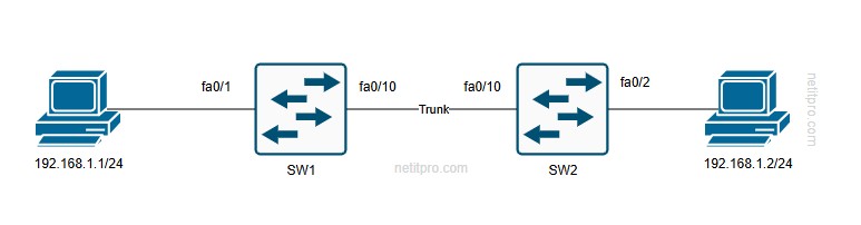
Let’s use a simple setup with two Catalyst switches, SW1 and SW2, linked together. SW1 connects to host H1, and SW2 to host H2. Our aim is to put both hosts in the same VLAN 20 and ensure the link between the switches carries that traffic via a trunk.
Creating VLAN 20 on Each Switch
Begin by defining the VLAN on SW1:
SW1(config)#vlan 20
SW1(config-vlan)#name Computers
SW1(config-vlan)#exit
Do the same on SW2:
SW2(config)#vlan 20
SW2(config-vlan)#name Computers
SW2(config-vlan)#exit
This step establishes VLAN 20, labeled “Computers,” on both devices. Without it, the switches won’t recognize the segment, and any ports assigned to it would fail to forward traffic properly.
Assigning Ports to VLAN 20
Next, configure the host-facing ports as access ports in VLAN 20. On SW1, for the interface to H1:
SW1(config)#interface fa0/1
SW1(config-if)#switchport access vlan 20
On SW2, for the interface to H2:
text
SW2(config)#interface fa0/2
SW2(config-if)#switchport access vlan 20
Access ports are straightforward—they belong to one VLAN and don’t tag frames. This ensures H1 and H2 send untagged traffic into VLAN 20. Remember, when devices communicate in the same VLAN across switches, the trunk will handle the tagging automatically.
Enabling the Trunk Link
Now, focus on the connection between SW1 and SW2, say on interface fa0/10. Trying to set it to trunk mode right away might hit a snag:
SW1(config)#interface fa0/10
SW1(config-if)#switchport mode trunk
Command rejected: An interface whose trunk encapsulation is "Auto" can not be configured to "trunk" mode.
The same happens on SW2. This error pops up because the switch defaults to negotiating encapsulation, and it won’t let you force trunk mode without specifying one first.
Choosing 802.1Q Encapsulation
Check your options with:
SW1(config-if)#switchport trunk encapsulation ?
  dot1q      Interface uses only 802.1q trunking encapsulation when trunking
  isl        Interface uses only ISL trunking encapsulation when trunking
  negotiate  Device will negotiate trunking encapsulation with peer on interface
Set it to 802.1Q on both ends:
SW1(config-if)#switchport trunk encapsulation dot1qAnd on SW2:
SW2(config-if)#switchport trunk encapsulation dot1q802.1Q is preferred because it’s open standard and works with non-Cisco gear. It adds a tag to the Ethernet frame, including fields like the Tag Protocol Identifier (TPID) set to 0x8100, Priority Code Point for QoS, Canonical Format Indicator, and the 12-bit VLAN ID. This tag ensures switches can demultiplex the traffic correctly. For deeper insight into frame structures, consider how this relates to Layer 3 headers in the Understanding the IPv4 Packet Header.
Confirming the Encapsulation Change
Run this on SW1:
SW1#show interfaces fa0/10 switchport
Name: Fa0/10
Switchport: Enabled
Administrative Mode: dynamic auto
Operational Mode: static access
Administrative Trunking Encapsulation: dot1q
You’ll see similar output on SW2. Notice the encapsulation is now dot1q, but the mode hasn’t shifted yet—it’s still set to dynamic auto, defaulting to access.
Activating Trunk Mode
With encapsulation sorted, enable the trunk:
SW1(config)#interface fa0/10
SW1(config-if)#switchport mode trunk
Repeat on SW2. Now verify:
SW1#show interfaces fa0/10 switchport
Name: Fa0/10
Switchport: Enabled
Administrative Mode: trunk
Operational Mode: trunk
Administrative Trunking Encapsulation: dot1q
Operational Trunking Encapsulation: dot1q
Both sides should match, confirming the trunk is up with 802.1Q in action. At this point, the link can carry tagged frames for multiple VLANs.
Checking Connectivity
From H1, ping H2 (assuming IPs like 192.168.1.1 and 192.168.1.2):
C:\>ping 192.168.1.2
Reply from 192.168.1.2: bytes=32 time<1ms TTL=128
Success means the trunk is working, allowing VLAN 20 traffic to cross. Behind the scenes, when H1 sends a frame, SW1 tags it on the trunk, and SW2 strips the tag before forwarding to H2. If the ping fails initially, it might involve address resolution—check out the understanding Address Resolution Protocol (ARP) for how MAC addresses are discovered in this process.
Useful Show Commands
Viewing VLAN Assignments
Use show vlan on SW2:
VLAN Name                             Status    Ports
---- -------------------------------- --------- -------------------------------
1    default                          active    Fa0/1, Fa0/3, ..., Fa0/24, Gi0/1, Gi0/2
20   Computers                        active    Fa0/2
Trunk ports won’t show here since this command lists only access ports per VLAN. It’s a quick way to confirm your access assignments.
Inspecting Trunk Details
Try show interfaces trunk or specifically show interfaces fa0/10 trunk:
text
Port        Mode             Encapsulation  Status        Native vlan
Fa0/10      on               802.1q         trunking      1

Port        Vlans allowed on trunk
Fa0/10      1-4094

Port        Vlans allowed and active in management domain
Fa0/10      1,20

Port        Vlans in spanning tree forwarding state and not pruned
Fa0/10      20
This breaks down the mode (“on” for active trunking), encapsulation, native VLAN (untagged, default 1), all allowed VLANs, active ones in the config, and those forwarding without pruning. Pruning removes unused VLANs to optimize bandwidth, a key STP feature.
Switchport Status for Access Ports
For the host port on SW2:
SW2#show interfaces fa0/2 switchport
Name: Fa0/2
Switchport: Enabled
Administrative Mode: static access
Operational Mode: static access
Compare to the trunk:
Administrative Mode: trunk
Operational Mode: trunk
This highlights the difference—access for single VLAN, trunk for multiples.
Available Port Modes
Query with switchport mode ?:
access        Set trunking mode to ACCESS unconditionally
dot1q-tunnel  set trunking mode to TUNNEL unconditionally
dynamic       Set trunking mode to dynamically negotiate access or trunk
private-vlan  Set private-vlan mode
trunk         Set trunking mode to TRUNK unconditionally
Under dynamic:
auto       Set trunking mode dynamic negotiation parameter to AUTO
desirable  Set trunking mode dynamic negotiation parameter to DESIRABLE
These options control how the port behaves during negotiation.
Exploring Dynamic Negotiation Modes
To see how ports decide their role, we’ll test combinations on fa0/10 between SW1 and SW2, observing with show interfaces switchport.
Both in Dynamic Auto
Set:
SW1(config-if)#switchport mode dynamic auto
SW2(config-if)#switchport mode dynamic auto
Outcome: Both end up as static access. Dynamic auto is passive—it won’t initiate a trunk, so they default to access.
Both in Dynamic Desirable
Configure:
SW1(config-if)#switchport mode dynamic desirable
SW2(config-if)#switchport mode dynamic desirable
Result: Trunk forms, operational mode trunk. Desirable actively negotiates, and since both want it, they agree.
Desirable on One, Auto on the Other
SW1(config-if)#switchport mode dynamic desirable
SW2(config-if)#switchport mode dynamic auto
Trunk establishes. The desirable side convinces the auto side to switch.
Auto on One, Trunk on the Other
SW1(config-if)#switchport mode dynamic auto
SW2(config-if)#switchport mode trunk
Trunk up. Auto accepts the fixed trunk proposal.
Auto on One, Access on the Other
SW1(config-if)#switchport mode dynamic auto
SW2(config-if)#switchport mode access
Both become access. No trunk push, so auto follows suit.
Desirable on One, Trunk on the Other
SW1(config-if)#switchport mode dynamic desirable
SW2(config-if)#switchport mode trunk
Trunk forms easily. Compatible intents.
Access on One, Trunk on the Other
SW1(config-if)#switchport mode access
SW2(config-if)#switchport mode trunk
SW1 stays access, SW2 trunk. But SW1 logs STP issues:
%SPANTREE-7-RECV_1Q_NON_TRUNK: Received 802.1Q BPDU on non trunk FastEthernet0/10 VLAN1.
%SPANTREE-7-BLOCK_PORT_TYPE: Blocking FastEthernet0/10 on VLAN0001. Inconsistent port type.
%SPANTREE-2-UNBLOCK_CONSIST_PORT: Unblocking FastEthernet0/10 on VLAN0001. Port consistency restored.
The access port gets tagged BPDUs it doesn’t expect, causing a brief block until STP resolves it. Avoid this in practice to prevent loops or outages.
In IP-based networks, understanding these Layer 2 mechanics ties into higher protocols—see the Introduction to Internet Protocol (IP) Version 4 for how packets traverse these setups.
Lets summarize this all into a table:
| Port Mode | Trunk | Access | Dynamic Auto | Dynamic Desirable |
| Trunk | Trunk | Limited | Trunk | Trunk |
| Access | Limited | Access | Access | Access |
| Dynamic Auto | Trunk | Access | Access | Trunk |
| Dynamic Desirable | Trunk | Access | Trunk | Trunk |
Wrapping Up
Configuring trunks involves creating VLANs, setting access ports, choosing encapsulation like 802.1Q, and enabling trunk mode explicitly for reliability. Dynamic modes like auto and desirable can automate this but introduce risks in production—better to hard-set trunks. Leverage show commands for verification to spot mismatches early.