Two switches. Four cables running between them. Spanning Tree blocking half of those links. Sound familiar? If you’ve ever looked at a network diagram and thought “there must be a better way,” EtherChannel is that better way.
EtherChannel — also called link aggregation — takes multiple physical connections between two switches and merges them into a single logical link. The result is increased bandwidth, built-in redundancy, and a topology that Spanning Tree doesn’t feel the need to break. In this guide, we’ll work through how EtherChannel actually functions, what requirements must be in place before you configure it, and how to set it up using all three available methods: PAgP, LACP, and manual mode.
Key Learnings
- EtherChannel bundles multiple physical interfaces into one logical port-channel interface.
- Spanning Tree sees the bundle as a single link — no loops, no blocked ports.
- Three configuration options exist: PAgP (Cisco-proprietary), LACP (IEEE standard), and manual (static, no negotiation).
- All physical member interfaces must share identical settings — speed, duplex, VLAN membership, and switchport mode must match across every link in the bundle.
- Load balancing distributes traffic across member links based on hashing algorithms using source/destination MAC or IP addresses.
- Up to 16 interfaces can be assigned to a single EtherChannel group, but only 8 can be active simultaneously. The remaining 8 act as hot standby links (LACP only).
- A single traffic flow is still bounded by the bandwidth of one physical link. Adding links increases aggregate throughput, not individual flow speed.
Prerequisites
Before working through this guide, you should be comfortable with:
- Basic Cisco IOS switch configuration and interface commands
- How Spanning Tree Protocol detects and prevents switching loops
- VLANs and the difference between access and trunk ports
- Trunk encapsulation, specifically 802.1Q — if you need a refresher, see “Understanding 802.1Q Encapsulation“
How EtherChannel Works
Let’s start with a scenario that justifies EtherChannel’s existence.
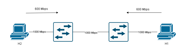
Imagine two switches connected by a single Gigabit Ethernet link. Host H1 is sending 600 Mbps of traffic toward H3, and Host H2 is also sending 600 Mbps toward H4. That’s 1200 Mbps of demand on a 1000 Mbps link. The link is the bottleneck.
There are two ways to fix this:
- Replace the link with a higher-speed connection — a 10 Gigabit interface, for example.
- Add more physical links and bundle them together using EtherChannel.
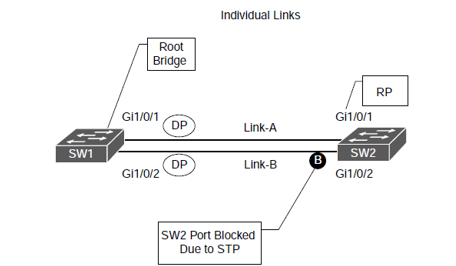
Option two is often cheaper and more practical, especially when the existing hardware already supports multiple Gigabit interfaces. So let’s say you cable up two additional links between the switches. Now you have three connections running in parallel.
The immediate problem: Spanning Tree sees those parallel links as a loop and blocks all but one. You’re back to a single active path.
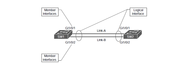
EtherChannel solves this by presenting all the physical links to Spanning Tree as a single logical interface — the port-channel interface. Spanning Tree never sees the individual member links. It sees one connection, calculates one path cost, and has nothing to block.
From a traffic perspective, EtherChannel distributes flows across the member links using a hashing algorithm. Different conversations take different paths, so the aggregate bandwidth available across all flows increases. Think of it like adding lanes to a motorway: the speed limit stays the same, but more vehicles can travel simultaneously without congestion.
If a physical member link fails, EtherChannel reconverges automatically. The remaining links continue forwarding traffic without Spanning Tree needing to recalculate or ports needing to transition through listening and learning states. Recovery is nearly instant.
Configuration
EtherChannel supports three configuration modes. We’ll walk through each one using two switches — SW1 and SW2 — each with two Gigabit Ethernet interfaces (GigabitEthernet 1/0/1 and 1/0/2) that we want to bundle together.
The topology is simple: SW1 and SW2 connected by two parallel Gigabit links.
PAgP
Port Aggregation Protocol (PAgP) is Cisco’s proprietary negotiation protocol for EtherChannel. It was developed after Cisco acquired the company Kalpana in 1994, which originally invented EtherChannel technology. Because it’s proprietary, PAgP only works between two Cisco devices.
PAgP has two operating modes:
- Desirable — The interface actively sends PAgP packets and initiates EtherChannel negotiation with the other side.
- Auto — The interface listens passively and will respond to PAgP negotiation, but won’t initiate it.
The combination of modes determines whether an EtherChannel forms:
| PagP Port Modes | Desirable | Auto |
|---|---|---|
| Desirable | Yes | Yes |
| Auto | Yes | No |
Two switches both set to Auto will never form an EtherChannel — neither side initiates. At least one end must be set to Desirable.
PagP Configuration
Here’s the configuration. On SW1, we’ll set both interfaces to Desirable mode:
SW1(config)# interface range GigabitEthernet 1/0/1 - 2
SW1(config-if-range)# channel-group 1 mode desirable
The channel-group command is what assigns physical interfaces to an EtherChannel group. The number (1 in this case) is locally significant — it just needs to be consistent across the interfaces you’re bundling. The moment you apply this command, IOS creates a virtual port-channel interface automatically.
On SW2, we’ll use Auto mode — it will wait for SW1 to initiate:
SW2(config)# interface range GigabitEthernet 1/0/1 - 2
SW2(config-if-range)# channel-group 1 mode auto
After a few seconds, you’ll see a log message confirming that Port-channel1 has come up. If you want to configure the EtherChannel as a trunk — which is common when carrying VLAN traffic between switches — do it on the port-channel interface, not on the physical members:
SW1(config)# interface Port-channel 1
SW1(config-if)# switchport trunk encapsulation dot1q
SW1(config-if)# switchport mode trunk
When you configure the port-channel interface, IOS automatically propagates those settings to all member interfaces. You should never configure the physical member interfaces directly — always make changes through the port-channel interface.
When trunking is configured this way, the physical interfaces inherit the dot1q encapsulation and trunk mode settings automatically. If you’re using VTP or need to control which VLANs are allowed across the trunk, those commands also go on the port-channel interface. For more on trunk configuration, see (Internal link suggestion: “Configure trunk ports on cisco switches”).
Verifying PAgP EtherChannel
The first verification command gives a high-level summary:
SW1# show etherchannel summary
Sample output:
Group  Port-channel  Protocol    Ports
------+-------------+-----------+---------------------------
1      Po1(SU)         PAgP      Gi1/0/1(P)   Gi1/0/2(P)
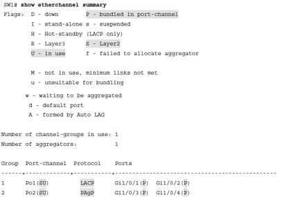
Reading the flags: SU on the port-channel means it’s a Layer 2 (S) channel that’s currently in use (U). The P flag next to each physical interface means it’s bundled and active in the port-channel. If you see I (stand-alone) or s (suspended), something is preventing the interface from joining — usually a configuration mismatch.
For more detail on the port-channel itself:
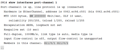
SW1# show interface port-channel 1
This output shows the protocol in use, how many ports are in the group, and the state of each member interface. You’ll also see a timestamp for when the last interface was bundled.
To inspect a specific physical interface and its EtherChannel relationship:
SW1# show interfaces GigabitEthernet 1/0/1 etherchannel
This gives you the local interface state, the mode it’s operating in, which port-channel it belongs to, and information about the neighbor switch — including the neighbor’s device ID and port.
Final PAgP Configuration
SW1:
hostname SW1
!
interface GigabitEthernet1/0/1
 switchport trunk encapsulation dot1q
 switchport mode trunk
 channel-group 1 mode desirable
!
interface GigabitEthernet0/2
 switchport trunk encapsulation dot1q
 switchport mode trunk
 channel-group 1 mode desirable
!
interface Port-channel1
 switchport trunk encapsulation dot1q
 switchport mode trunk
!
end
SW2:
hostname SW2
!
interface GigabitEthernet1/0/1
 switchport trunk encapsulation dot1q
 switchport mode trunk
 channel-group 1 mode auto
!
interface GigabitEthernet0/2
 switchport trunk encapsulation dot1q
 switchport mode trunk
 channel-group 1 mode auto
!
interface Port-channel1
 switchport trunk encapsulation dot1q
 switchport mode trunk
!
end
LACP
Link Aggregation Control Protocol (LACP) is the IEEE 802.3ad standard for EtherChannel negotiation. Because it’s an open standard, LACP works between devices from different vendors — Cisco to HP, Cisco to Juniper, and so on. For any multi-vendor environment, LACP is the correct choice.
LACP uses different mode names than PAgP, but the logic is the same:
- Active — The interface sends LACP packets and actively tries to form an EtherChannel.
- Passive — The interface listens for LACP packets and responds, but doesn’t initiate.
Formation rules:
| LACP Port Modes | Active | Passive |
|---|---|---|
| Active | Yes | Yes |
| Passive | Yes | No |
Two Passive interfaces will not form an EtherChannel, for the same reason as PAgP Auto/Auto — no one initiates. At least one side must be Active.
LACP also introduces the concept of hot standby links. When you assign more than 8 interfaces to a channel group, LACP keeps the best 8 active (based on port priority) and holds the remaining interfaces in standby. If an active link fails, a standby link takes over almost immediately. PAgP and manual mode don’t support this behavior.
Configure SW1 in Active mode:
SW1(config)# interface range GigabitEthernet 1/0/1 - 2
SW1(config-if-range)# channel-group 1 mode active
Configure SW2 in Passive mode:
SW2(config)# interface range GigabitEthernet 1/0/1 - 2
SW2(config-if-range)# channel-group 1 mode passive
Verify with show etherchannel summary:
Group  Port-channel  Protocol    Ports
------+-------------+-----------+---------------------------
1      Po1(SU)         LACP      Gi1/0/1(P)   Gi1/0/2(P)
The output looks nearly identical to the PAgP output, except the Protocol column now shows LACP. Notice that the LACP-specific flag H (Hot-standby) appears in the legend — you’d see it next to any interfaces sitting in standby.
The show interfaces GigabitEthernet 1/0/1 etherchannel output for LACP differs slightly from PAgP. Instead of PAgP-specific fields like Hello timer and PAgP flags, you’ll see LACP-specific fields: LACP port priority, Admin Key, Oper Key, Port Number, and Port State. The partner information section shows the same fields for the remote switch. These values are used by LACP to determine which ports participate in the active bundle and which enter standby.
Final LACP Configuration
SW1:
hostname SW1
!
interface GigabitEthernet1/0/1
 channel-group 1 mode active
!
interface GigabitEthernet1/0/2
 channel-group 1 mode active
!
interface Port-channel1
!
end
SW2:
hostname SW2
!
interface GigabitEthernet1/0/1
 channel-group 1 mode passive
!
interface GigabitEthernet1/0/2
 channel-group 1 mode passive
!
interface Port-channel1
!
end
Manual EtherChannel
It’s possible to build an EtherChannel without using any negotiation protocol at all. This is called static or manual mode, configured with the keyword on.
When both sides are set to on, the interfaces immediately join the channel group — no negotiation happens. There’s no protocol exchanging hellos or verifying compatibility. The switch just assumes the other end is configured the same way and brings the channel up.
SW1(config)# interface range GigabitEthernet 1/0/1 - 2
SW1(config-if-range)# channel-group 1 mode on
SW2(config)# interface range GigabitEthernet 1/0/1 - 2
SW2(config-if-range)# channel-group 1 mode on
One important rule: you cannot mix on with PAgP or LACP modes. If one side is on and the other is desirable or active, the EtherChannel will not form. Both sides must use on for static mode to work.
The lack of negotiation is both the advantage and the risk of manual mode. There’s no overhead, but there’s also no protection against misconfiguration. If the interfaces on one side have a different VLAN configuration or duplex setting, PAgP and LACP would detect the inconsistency and prevent a flawed channel from forming. Manual mode won’t catch it — the channel comes up regardless, and you may see traffic issues that are difficult to troubleshoot.
Verification looks the same as before:
SW1# show etherchannel summary
Group  Port-channel  Protocol    Ports
------+-------------+-----------+---------------------------
1      Po1(SU)           -       Gi1/0/1(P)   Gi1/0/2(P)
The Protocol column shows a dash (-) instead of PAgP or LACP. That’s the tell-tale sign of a manually configured EtherChannel.
The show etherchannel 1 port-channel output confirms the EC state for each interface shows On rather than Desirable-Sl or Active.
Final Manual Configuration
SW1:
hostname SW1
!
interface GigabitEthernet1/0/1
 channel-group 1 mode on
!
interface GigabitEthernet1/0/2
 channel-group 1 mode on
!
interface Port-channel1
!
end
SW2:
hostname SW2
!
interface GigabitEthernet1/0/1
 channel-group 1 mode on
!
interface GigabitEthernet1/0/2
 channel-group 1 mode on
!
interface Port-channel1
!
end
Load Balancing
EtherChannel doesn’t randomly scatter packets across physical links. It uses a hashing algorithm to make consistent forwarding decisions, ensuring that all frames belonging to the same flow always exit the same physical interface. This is critical — if frames within a single TCP session arrived out of order because they took different physical paths at different speeds, the session would suffer serious performance problems.
The hash is computed from fields in the frame or packet header. Cisco switches support multiple load-balancing methods, and the options available depend on the platform. Common choices include:
Load Balancing Hash Options
- Destination MAC address
- Destination IP address
- Destination IP address and destination TCP/UDP port
- Destination TCP/UDP port
- Source and destination IP addresses only
- Source and destination MAC addresses
- Source and destination IP addresses and source and destination TCP/UDP ports
- Source and destination TCP/UDP ports only
- Source IP address
- Source MAC address
- Source and destination MAC address (XOR of both)
The switch computes the hash and maps the result to one of the active member links. Frames with the same hash value always take the same link.
To check the current load-balancing method:
SW1# show etherchannel load-balance
To change it:
SW1(config)# port-channel load-balance src-dst-ip
Choosing the right method matters in practice. If all your traffic comes from a single source host, source-MAC-based hashing will put everything on one link regardless of how many member links exist — the hash always returns the same value for the same source. In that case, switching to source-destination IP or destination MAC will distribute the load more evenly across links.
For environments running VLANs across trunked EtherChannels, it’s worth understanding how VLAN tags interact with the forwarding decision. The 802.1Q tag is added to frames traversing a trunk — the EtherChannel load balancing hash may or may not consider the VLAN tag, depending on the platform and configured method. For a deeper look at how 802.1Q tagging works, see (Internal link suggestion: “Understanding 802.1Q Encapsulation”). If you’re using DTP to negotiate trunk status dynamically, see (Internal link suggestion: “Dynamic Trunking Protocol”) for how that negotiation interacts with EtherChannel member interfaces.
Summary
EtherChannel is one of those technologies that solves a real, practical problem — you need more bandwidth between two switches, and adding physical links without it just causes Spanning Tree headaches. Bundling those links into a port-channel gives you the aggregate throughput, the redundancy, and a clean single-link view for STP.
The three configuration options cover every scenario: PAgP when both ends are Cisco and you want Cisco’s proprietary negotiation, LACP when you’re in a multi-vendor environment or simply want the IEEE standard, and manual mode when you need something simple and can guarantee the configuration is correct on both ends. In most enterprise deployments, LACP is the preferred choice because of its flexibility and the hot standby link feature.
Prepare for the Exam
A few things to keep in mind that frequently appear on the exam:
- Always configure EtherChannel settings (trunking, VLANs, speed, duplex) on the port-channel interface, never directly on the physical member interfaces.
- PAgP Auto + Auto = no channel. LACP Passive + Passive = no channel. One side always needs to be the initiator.
- Manual mode (
on) cannot be combined with PAgP or LACP on the opposite end. - The
show etherchannel summarycommand is your fastest way to confirm whether a channel is up and which protocol it’s using. - Interface mismatches — different native VLANs, different allowed VLANs, different duplex settings — will prevent PAgP and LACP from forming a channel. Manual mode will form the channel anyway, which is why mismatches are harder to catch with static configuration.
If your network uses VTP to synchronize VLAN databases across switches, the EtherChannel trunk will carry VTP advertisements just like any other trunk link — see (Internal link suggestion: “VLAN Trunking Protocol”) for how VTP interacts with trunk ports in general.
EtherChannel sits at the intersection of switching, spanning tree, and VLAN trunking — understanding it well ties together a significant portion of the CCNA switching curriculum.