Most people encounter EtherChannels in their Layer 2 form — bundled trunk links carrying VLANs between switches. But there’s another variation that doesn’t get as much attention: the Layer 3 EtherChannel. If you’ve already worked through “EtherChannels“, this is the natural next step. You’ll see how to take that same link-bundling concept and apply it at the routing layer, turning a port-channel into something that behaves like a routed interface rather than a switchport.
What Is a Layer 3 EtherChannel?
A Layer 3 EtherChannel is a port-channel interface converted from a switched interface into a routed one. Instead of forwarding frames based on MAC address tables, the switch routes IP packets through this interface. It works just like a router physical port.
This distinction matters. A standard Layer 2 EtherChannel carries VLANs and participates in Spanning Tree. A Layer 3 EtherChannel gets an IP address assigned directly to it. No VLANs, no trunking — just routed traffic across a logical bundle of physical links.
The practical benefit is bandwidth aggregation with routing. Say you have two 1 Gbps links between two distribution-layer switches. You want to route between subnets across them without a dedicated router. A Layer 3 EtherChannel lets you do exactly that.
Network Topology
For this example, two Cisco IOS switches connect to each other using two GigabitEthernet links. Both physical links bundle into a single port-channel interface. Each switch gets an IP address on that port-channel.
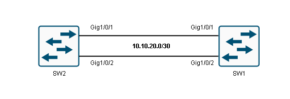
SW1: Port-Channel 12 → 10.10.20.1/30
SW2: Port-Channel 12 → 10.10.20.2/30
This is a point-to-point Layer 3 link, similar to what you’d see between two routers connected by a serial or Ethernet cable.
Prerequisites
Before applying the channel-group command to any interface, every physical interface in the bundle must have identical configuration. This is the same rule that applies to Layer 2 EtherChannels — speed, duplex, and mode settings must match across all member links.
The additional requirement for a Layer 3 EtherChannel is the no switchport command. By default, Cisco IOS switch interfaces are Layer 2 switchports. If you forget to remove that switchport behavior before creating the channel group, the resulting port-channel will be Layer 2, not Layer 3. This is a common mistake and worth double-checking before you proceed.
The no switchport command must be applied to each physical interface individually, before those interfaces are bundled.
Configuration on SW1
Start by selecting the physical interfaces that will form the bundle, then convert them to routed mode and assign them to the channel group.
SW1(config)# interface range GigabitEthernet 1/0/1 - 2
SW1(config-if-range)# no switchport
SW1(config-if-range)# channel-group 12 mode on
Creating a port-channel interface Port-channel 12
The no switchport command removes the Layer 2 behavior from each interface, making them act like router ports. The channel-group 12 mode on command assigns both interfaces to channel group 12 and forces them into the bundle unconditionally — no negotiation protocol (like LACP or PAgP) is used when mode on is specified.
Once you run this, IOS automatically creates the virtual Port-channel 12 interface. Now assign an IP address to it:
SW1(config)# interface port-channel 12
SW1(config-if)# ip address 10.10.20.1 255.255.255.252
SW1(config-if)# no shutdown
A /30 subnet is a natural choice here since this is a point-to-point link with only two hosts (the two switches).
Configuration on SW2
Mirror the configuration on the second switch:
SW2(config)# interface range GigabitEthernet 1/0/1 - 2
SW2(config-if-range)# no switchport
SW2(config-if-range)# channel-group 12 mode on
Creating a port-channel interface Port-channel 12
SW2(config)# interface port-channel 12
SW2(config-if)# ip address 10.10.20.2 255.255.255.252
SW2(config-if)# no shutdown
The channel group number (12 in this case) is locally significant — it doesn’t need to match between the two switches. What matters is that the physical interfaces on each end are compatible and that the port-channel interface inherits the correct settings.
Verifying the Layer 3 EtherChannel
Once both switches are configured, use show etherchannel summary to confirm the bundle is active and operating in Layer 3 mode.
SW1# show etherchannel 12 summary
Flags:  D - down        P - bundled in port-channel
        I - stand-alone s - suspended
        H - Hot-standby (LACP only)
        R - Layer3      S - Layer2
        U - in use      f - failed to allocate aggregator
        M - not in use, minimum links not met
        u - unsuitable for bundling
        w - waiting to be aggregated
        d - default port

Number of channel-groups in use: 1
Number of aggregators:           1

Group  Port-channel  Protocol    Ports
------+-------------+-----------+-------------------------------
12     Po12(RU)         -        Gi1/0/1(P)   Gi1/0/2(P)
This output tells you a lot. Look at the flags next to Po12 — R means Layer 3, and U means in use. Together, RU confirms the port-channel is a routed interface and is operational. The P flag next to each physical interface means it’s actively bundled and passing traffic.
If you saw S instead of R, that would indicate a Layer 2 EtherChannel — meaning the no switchport command was likely missed on one or more physical interfaces.
The Protocol column shows a dash, which is expected when mode on is used since no negotiation protocol is running. If you were using LACP, you’d see LACP here instead.
Understanding the Flag Table
The flag section at the top of the show etherchannel summary output is worth understanding in detail, because these flags appear on the exam and in real-world troubleshooting.
D means the interface or port-channel is down. P on a physical interface confirms it’s successfully bundled into the port-channel. I means stand-alone — the interface is not part of any bundle, usually because negotiation failed. s means suspended, which typically indicates a configuration mismatch between member interfaces. H is Hot-standby and only appears with LACP. R and S distinguish Layer 3 from Layer 2 mode. U confirms the port-channel is active and carrying traffic. f indicates a failure to allocate the aggregator, which is a hardware resource issue on some platforms. M means minimum links haven’t been met — a condition triggered when you configure port-channel min-links.
Knowing what each flag means lets you diagnose problems quickly. If you see s on a physical interface, your first step is to compare its configuration against the other member interfaces and look for mismatches.
How the IP Address Inheritance Works
When you run channel-group on a physical interface, the port-channel interface is created automatically. The physical interfaces themselves do not hold IP addresses — the IP address lives on the port-channel interface, and all traffic enters and exits through the logical bundle.
This is the same model as a regular router interface or an SVI, just applied to a bundled link. The switch uses the port-channel interface as its routing reference, and the physical links handle the actual frame delivery across the wire. Load balancing across member links still happens, based on the switch’s configured hashing algorithm (source/destination MAC, IP, or port, depending on the platform and settings).
Because this interface is now a routed port, you won’t see it participating in Spanning Tree. That’s another advantage of Layer 3 EtherChannels at the distribution layer — they sidestep STP entirely for inter-switch routing links, which simplifies topology and speeds up convergence. If you’re familiar with “VLAN Trunking Protocol“) and how VLAN information propagates through a network, you’ll notice that a Layer 3 EtherChannel sits outside that domain entirely.
Relationship to Trunking and VLANs
A Layer 2 EtherChannel often operates as a trunk, carrying multiple VLANs between switches. That model works well for access-layer redundancy and is commonly paired with “Dynamic Trunking Protocol” to negotiate the trunk automatically.
A Layer 3 EtherChannel takes a different approach. Since the port-channel is a routed interface, it doesn’t carry VLAN tags. It’s a pure IP link. If you need inter-VLAN routing across the bundle, you’d configure that at the routing protocol level — for example, by running OSPF over the Layer 3 EtherChannel between two multilayer switches.
This is why Layer 3 EtherChannels are most common at the distribution and core layers of a campus network, where routing decisions happen, rather than at the access layer where VLAN-based switching dominates.
Summary
A Layer 3 EtherChannel converts a bundle of physical switch interfaces into a single routed interface. The key steps are: remove the switchport behavior with no switchport on each physical interface, assign the interfaces to a channel group, and then configure the IP address on the resulting port-channel interface — not on the physical members.
The show etherchannel summary command is your primary verification tool. The R and U flags in the output confirm a healthy Layer 3 bundle. Any s (suspended) or missing P flags on member ports indicate a configuration mismatch that needs investigation.
At the CCNA level, the main things to remember are that forgetting no switchport produces a Layer 2 result instead of Layer 3, and that the IP address always belongs to the port-channel interface. Get those two points right and the rest of the configuration follows naturally.