In this lesson I will explain how PVST+ works and how Cisco switches use it to build a separate loop-free topology for every VLAN.
Why Do We Need PVST+?
Before we talk about PVST+, let me remind you why we have Spanning Tree Protocol at all.
When you connect switches together with redundant links — which you should always do for reliability — you accidentally create loops. Layer 2 has no TTL field like IP does, so a broadcast frame that enters a loop will circulate forever, consuming every switch’s CPU and crashing your network in seconds. We call this a broadcast storm.
STP solves the problem by blocking one or more ports, turning your looped physical topology into a loop-free logical one.
The original IEEE 802.1D STP, however, has a big limitation: it runs one single spanning tree for all VLANs. This is called Common Spanning Tree (CST). Think about what that means in practice. If you have 100 VLANs, every single one of them uses the same blocked port, regardless of what traffic they carry. A link that could be actively forwarding traffic for 50 of your VLANs just sits idle — completely wasted.
PVST+ (Per-VLAN Spanning Tree Plus) is Cisco’s answer to this. It runs a completely independent STP instance for every VLAN. Each VLAN elects its own root bridge, makes its own port role decisions, and has its own blocked port. This means you can actually use your redundant links by having different VLANs take different paths through the network.
PVST+ is the default spanning tree mode on Cisco Catalyst switches. From IOS 15.2(4)E onwards, the default is Rapid PVST+, which is the faster version. We will cover that in a separate lesson.
The Topology
Let me show you the topology we will use throughout this lesson. We have three switches — SW1, SW2, and SW3 — connected in a triangle. This is the most classic redundant switched design you will see in real networks.
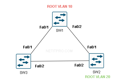
The connections are:
| Link | SW1 Port | Remote Switch | Remote Port |
|---|---|---|---|
| SW1 ↔ SW3 | Fa0/1 | SW3 | Fa0/1 |
| SW1 ↔ SW2 | Fa0/2 | SW2 | Fa0/1 |
| SW3 ↔ SW2 | Fa0/2 | SW2 | Fa0/2 |
We have two VLANs in use: VLAN 10 and VLAN 20. Both VLANs are trunked across all three links so every switch can carry both VLANs.
SW1 is the root bridge for both VLAN 10 and VLAN 20 in this example.
How Does PVST+ Elect a Root Bridge?
Before we can understand port roles, we need to understand how PVST+ decides which switch becomes the root bridge. The process is identical to 802.1D STP — but it happens separately, once per VLAN.
When a Cisco switch boots, it does not know anything about the network yet. It assumes that it is the root bridge and starts sending special frames out of every port. These frames are called BPDUs — Bridge Protocol Data Units. Think of a BPDU as a switch saying: “Hey, I think I am the root bridge, here is my information.”
Every switch receives BPDUs from its neighbors and compares them to its own. The comparison is based on the Bridge ID (BID).
What is a Bridge ID?
A Bridge ID is a unique identifier for each switch, and it has three parts:
[ Priority (4 bits) ] [ Extended System ID / VLAN ID (12 bits) ] [ MAC Address (48 bits) ]
Let me break that down:
- Priority — A configurable value. The default is 32768. You can set it in increments of 4096 (so 0, 4096, 8192, 16384… up to 61440).
- Extended System ID — This is automatically set to the VLAN number. So for VLAN 10, this field is 10. For VLAN 20, it is 20.
- MAC Address — The switch’s base MAC address. This is the final tiebreaker.
So for a switch with the default priority running VLAN 10, its Bridge ID priority field shows as 32768 + 10 = 32778.
The switch with the lowest Bridge ID wins the root bridge election. If two switches have the same priority (which they do by default), the switch with the lowest MAC address becomes root.
Key point for beginners: Lower is always better in spanning tree elections. Lowest Bridge ID = root bridge winner. Lowest path cost = best path to root. Lowest port ID = tiebreaker for equal-cost paths.
Step 1 — Root Bridge Election
In our topology, all three switches boot up with the default priority of 32768. PVST+ runs this election separately for each VLAN.
Let us say the MAC addresses are:
| Switch | MAC Address |
|---|---|
| SW1 | 0001.0001.0001 |
| SW2 | 0002.0002.0002 |
| SW3 | 0003.0003.0003 |
For VLAN 10:
- SW1 BID = 32778 : 0001.0001.0001
- SW2 BID = 32778 : 0002.0002.0002
- SW3 BID = 32778 : 0003.0003.0003
SW1 has the lowest MAC address, so SW1 wins and becomes the root bridge for VLAN 10.
For VLAN 20:
- SW1 BID = 32788 : 0001.0001.0001
- SW2 BID = 32788 : 0002.0002.0002
- SW3 BID = 32788 : 0003.0003.0003
Again SW1 has the lowest MAC address, so SW1 is also root bridge for VLAN 20.
In a well-designed network you would manually configure different root bridges per VLAN so that different VLANs use different paths. We will talk about that configuration at the end. For now, SW1 is root for both VLANs — which is perfectly valid for learning purposes.
Step 2 — Port Roles
Once the root bridge is elected, every switch needs to figure out the role of each of its ports. PVST+ defines three port roles:
| Port Role | Abbreviation | What it Does |
|---|---|---|
| Root Port | RP | The single best port on a non-root switch that leads toward the root bridge |
| Designated Port | DP | The best port on each network segment for reaching the root |
| Blocked Port | BLK | A port that is shut down logically to prevent a loop |
Here is the rule of thumb:
- The root bridge has all ports as Designated Ports. It is the center of the tree, so all its ports face away from the root — they are all designated.
- Every non-root switch has exactly one Root Port — the best port facing toward the root.
- On each segment between two switches, one switch wins the Designated Port election for that segment. The losing switch’s port becomes Blocked.
How Does a Switch Choose Its Root Port?
A non-root switch looks at every port that receives BPDUs from the root and calculates the Root Path Cost — the total cost of the path from that port all the way to the root bridge.
Port cost is determined by link speed. The default costs are:
| Link Speed | STP Port Cost (802.1D) |
|---|---|
| 10 Mbps | 100 |
| 100 Mbps (FastEthernet) | 19 |
| 1 Gbps (GigabitEthernet) | 4 |
| 10 Gbps | 2 |
In our topology, all links are FastEthernet, so every link has a cost of 19.
Port Roles — VLAN 10 Walkthrough
Let me now walk through the port role assignment for VLAN 10 step by step.
SW1 (Root Bridge)
SW1 is the root bridge. It does not need to calculate a path to the root because it is the root. Its path cost to itself is zero.
- SW1 Fa0/1 → Designated Port (faces the SW3 segment)
- SW1 Fa0/2 → Designated Port (faces the SW2 segment)
All ports on the root bridge are Designated Ports. Always.
SW2 — Choosing a Root Port
SW2 has two paths to reach the root bridge SW1:
Path 1: SW2 Fa0/1 → directly to SW1 Fa0/2 Cost = 19 (one hop, one FastEthernet link)
Path 2: SW2 Fa0/2 → SW3 Fa0/2 → SW3 Fa0/1 → SW1 Fa0/1 Cost = 19 + 19 = 38 (two hops, two FastEthernet links)
SW2 picks the path with the lowest cost. Path 1 wins with cost 19.
- SW2 Fa0/1 → Root Port ✅ (best path to root, cost 19)
- SW2 Fa0/2 → will be determined next
SW3 — Choosing a Root Port
SW3 also has two paths:
Path 1: SW3 Fa0/1 → directly to SW1 Fa0/1 Cost = 19
Path 2: SW3 Fa0/2 → SW2 Fa0/2 → SW2 Fa0/1 → SW1 Fa0/2 Cost = 19 + 19 = 38
Path 1 wins with cost 19.
- SW3 Fa0/1 → Root Port ✅ (best path to root, cost 19)
- SW3 Fa0/2 → will be determined next
The SW2–SW3 Segment — Designated Port Election
Now we have one segment left: the link between SW3 Fa0/2 and SW2 Fa0/2. Neither of these ports has been assigned a role yet.
On every segment in the network, STP elects exactly one Designated Port. The switch that wins the Designated Port election is the one with the best path to the root bridge from that segment.
Let us compare:
| SW2 side (Fa0/2) | SW3 side (Fa0/2) | |
|---|---|---|
| Root Path Cost | 19 (via Fa0/1 → SW1) | 19 (via Fa0/1 → SW1) |
| Bridge ID | 32778 : 0002.0002.0002 | 32778 : 0003.0003.0003 |
Both SW2 and SW3 have equal root path cost (19) to reach SW1. So we go to the tiebreaker: lowest Bridge ID wins. SW2’s MAC address (0002.0002.0002) is lower than SW3’s (0003.0003.0003).
SW2 wins the Designated Port election for this segment.
- SW2 Fa0/2 → Designated Port ✅
- SW3 Fa0/2 → Blocked Port 🚫
This blocked port is what breaks the loop. VLAN 10 traffic can no longer loop around the triangle because SW3’s Fa0/2 is shut down logically by STP.
Port Roles — VLAN 20 Walkthrough
Now PVST+ runs the exact same process independently for VLAN 20.
SW1 is the root bridge for VLAN 20 as well. Every switch recalculates port roles using the same path cost logic — and since the physical topology is identical and no priorities have been changed, the result is the same:
| Switch | Port | VLAN 20 Role |
|---|---|---|
| SW1 | Fa0/1 | Designated Port |
| SW1 | Fa0/2 | Designated Port |
| SW2 | Fa0/1 | Root Port |
| SW2 | Fa0/2 | Designated Port |
| SW3 | Fa0/1 | Root Port |
| SW3 | Fa0/2 | Blocked |
The same port ends up blocked for both VLANs. This is fine for a lab, but in production you would configure SW2 or SW3 as root for VLAN 20 so that the other link carries traffic. We will get to that.
Complete Port Role Summary
Here is the full picture for both VLANs:
| Switch | Port | VLAN 10 Role | VLAN 20 Role | State |
|---|---|---|---|---|
| SW1 | Fa0/1 | Designated | Designated | Forwarding |
| SW1 | Fa0/2 | Designated | Designated | Forwarding |
| SW2 | Fa0/1 | Root Port | Root Port | Forwarding |
| SW2 | Fa0/2 | Designated | Designated | Forwarding |
| SW3 | Fa0/1 | Root Port | Root Port | Forwarding |
| SW3 | Fa0/2 | Blocked | Blocked | Blocking |
Step 3 — Port States
Port roles tell a port what it is. Port states tell a port what it is allowed to do. Before a port starts forwarding traffic it must go through a series of states.
Blocking → Listening → Learning → Forwarding
| State | Can Receive BPDUs? | Can Send BPDUs? | Learns MACs? | Forwards Frames? | Time |
|---|---|---|---|---|---|
| Blocking | Yes | No | No | No | 20 sec (Max Age) |
| Listening | Yes | Yes | No | No | 15 sec (Forward Delay) |
| Learning | Yes | Yes | Yes | No | 15 sec (Forward Delay) |
| Forwarding | Yes | Yes | Yes | Yes | — |
Let me explain what is happening in each state:
Blocking — The port is receiving BPDUs and listening to the network to figure out its role. It does not forward any user traffic and it does not learn MAC addresses. A port stays here for up to 20 seconds (the Max Age timer).
Listening — The port has decided it should be a Root Port or Designated Port. It starts sending BPDUs and participating in STP, but it still does not learn MAC addresses or forward user frames. This lasts 15 seconds.
Learning — The port is now building its MAC address table. It still does not forward user frames, but when frames arrive, it notes the source MAC address. This also lasts 15 seconds. The reason we have this state is to prevent a traffic black-hole — by the time the port starts forwarding, it already knows where most devices are.
Forwarding — The port is fully active. It forwards user traffic, learns MAC addresses, and sends/receives BPDUs normally.
Total convergence time for classic PVST+: 30 seconds (15 sec Listening + 15 sec Learning) from the moment a port decides to transition to Forwarding. From a link failure, add the 20 second Max Age timer = 50 seconds total. This is why Rapid PVST+ was invented — it converges in under a second.
How Do Switches Know About Topology Changes?
When a link goes down — say SW3’s Fa0/1 fails — SW3 notices immediately. It then needs to tell the rest of the network so that switches can flush their MAC address tables and avoid sending traffic down the dead path.
SW3 sends a special BPDU called a TCN — Topology Change Notification — upstream toward the root bridge. Every switch that receives a TCN acknowledges it and passes it along toward root.
Once SW1 (the root bridge) receives the TCN, it sets the TC bit (Topology Change bit) in its own Hello BPDUs and floods those BPDUs to every switch in the network. This tells every switch: “Something changed, age out your MAC table faster.” Switches reduce their MAC aging timer from the default 300 seconds down to 15 seconds so they relearn where devices are quickly.
Verifying PVST+ on Cisco IOS
Let us look at what you would see on a real Cisco switch. On SW1 you would run:
SW1#show spanning-tree vlan 10

VLAN0010
  Spanning tree enabled protocol ieee
  Root ID    Priority    32778
             Address     0001.0001.0001
             This bridge is the root
             Hello Time   2 sec  Max Age 20 sec  Forward Delay 15 sec

  Bridge ID  Priority    32778  (priority 32768 sys-id-ext 10)
             Address     0001.0001.0001
             Hello Time   2 sec  Max Age 20 sec  Forward Delay 15 sec
             Aging Time  300 sec

Interface        Role Sts Cost      Prio.Nbr Type
---------------- ---- --- --------- -------- --------------------------------
Fa0/1            Desg FWD 19        128.1    P2p
Fa0/2            Desg FWD 19        128.2    P2p
You can see:
- “This bridge is the root” — SW1 knows it is the root for VLAN 10
- Priority 32778 = 32768 (default) + 10 (VLAN ID)
- Both ports show Desg FWD — Designated, Forwarding
- Cost is 19 — FastEthernet
Now let us check SW3:
SW3#show spanning-tree vlan 10

VLAN0010
  Spanning tree enabled protocol ieee
  Root ID    Priority    32778
             Address     0001.0001.0001
             Cost        19
             Port        1 (FastEthernet0/1)
             Hello Time   2 sec  Max Age 20 sec  Forward Delay 15 sec

  Bridge ID  Priority    32778  (priority 32768 sys-id-ext 10)
             Address     0003.0003.0003
             Hello Time   2 sec  Max Age 20 sec  Forward Delay 15 sec
             Aging Time  300 sec

Interface        Role Sts Cost      Prio.Nbr Type
---------------- ---- --- --------- -------- --------------------------------
Fa0/1            Root FWD 19        128.1    P2p
Fa0/2            Altn BLK 19        128.2    P2p
You can see:
- SW3 knows the root bridge is SW1 (address 0001.0001.0001)
- SW3 reaches the root via Fa0/1 (the Root Port) at a cost of 19
- Fa0/2 shows Altn BLK — Alternate, Blocking. This is the blocked port that prevents the loop.
Note: Cisco IOS uses Altn (Alternate) instead of just “Blocked” in show output. The Alternate port is a port that has a valid path to the root but is being blocked because a better path exists elsewhere. The behavior is the same — it does not forward user traffic.
Why Is the Same Port Blocked for Both VLANs?
In our topology, SW3 Fa0/2 is blocked for both VLAN 10 and VLAN 20. You might be wondering — if PVST+ runs separate instances, why are both instances blocking the same port?
The answer is: because we have not changed any priorities. When all switches use the default priority, the root bridge election is decided purely by MAC address. SW1 wins for all VLANs. And since SW1 is at the top of the triangle for both VLANs, the port that gets blocked will always be the same one — the furthest link from the root on the “losing” side of the triangle.
PVST+ gives you the ability to use different paths per VLAN. But you have to configure it intentionally. Left at default settings with one root bridge, all instances block the same port and you get no load balancing benefit.
Configuring the Root Bridge Per VLAN
Here is how you make PVST+ actually useful. Let us say you want:
- SW1 = Root Bridge for VLAN 10
- SW2 = Root Bridge for VLAN 20
This means VLAN 10 blocks one port and VLAN 20 blocks a different port, distributing traffic across your redundant links.
Option 1 — Use the root primary macro (recommended for simplicity):
SW1(config)#spanning-tree vlan 10 root primary
SW2(config)#spanning-tree vlan 20 root primary
This command automatically lowers the switch’s priority to 24576 (or lower if needed) to guarantee it wins the election. It is a smart command — if another switch already has a priority lower than 24576, this command will go one step lower to beat it.
Option 2 — Set priority manually:
SW1(config)#spanning-tree vlan 10 priority 4096
SW2(config)#spanning-tree vlan 20 priority 4096
Priority 4096 is very low (remember, lower wins), so these switches will definitely become root for their respective VLANs. You should set it in multiples of 4096.
After this configuration, VLAN 10 traffic flows through SW1 as root, and the blocked port for VLAN 10 will be on the SW2–SW3 segment on the SW3 side. VLAN 20 traffic flows through SW2 as root, and the blocked port for VLAN 20 will be on the SW1–SW3 segment on the SW3 side. Now both redundant links carry traffic for at least one VLAN — no wasted links.
Summary
Let me summarize everything we covered in this lesson:
- PVST+ runs a separate STP instance for every VLAN, giving you per-VLAN root bridge election and per-VLAN port role decisions.
- The root bridge is elected based on lowest Bridge ID (priority + VLAN ID + MAC address).
- Every non-root switch selects a Root Port — the port with the lowest cost path to root.
- On each segment, one switch wins the Designated Port election. The loser’s port is Blocked.
- Ports transition through Blocking → Listening → Learning → Forwarding, which takes 30 seconds under classic PVST+.
- By default, all VLANs elect the same root bridge (lowest MAC wins), so the same port gets blocked for every VLAN. This wastes your redundant links.
- To get real load balancing, configure different root bridges per VLAN using
spanning-tree vlan X root primaryorspanning-tree vlan X priority. - In production, use Rapid PVST+ (
spanning-tree mode rapid-pvst) to get sub-second convergence instead of the 30–50 seconds of classic PVST+.
In the next lesson we will look at Rapid PVST+ and how it achieves near-instant convergence using the Proposal/Agreement mechanism.