If you’ve studied the OSI model and how data moves through network layers (check out our detailed guide on the OSI Model for a refresher), you know that local communication between devices on the same LAN relies on both logical (IP) and physical (MAC) addressing.
When two hosts want to exchange data:
- An IP packet is built at Layer 3 with source and destination IPv4 addresses.
- This packet gets encapsulated into an Ethernet frame at Layer 2, needing source and destination MAC addresses.
The sender always knows its own MAC address, but discovering the destination’s MAC? That’s the job of ARP (Address Resolution Protocol). ARP dynamically resolves an unknown MAC address from a known IPv4 address within the same subnet, making local IP communication possible.
In this CCNA-focused guide, we’ll walk through ARP step by step with clear examples, packet breakdowns, and Wireshark captures.
ARP in Action: A Practical Ping Example
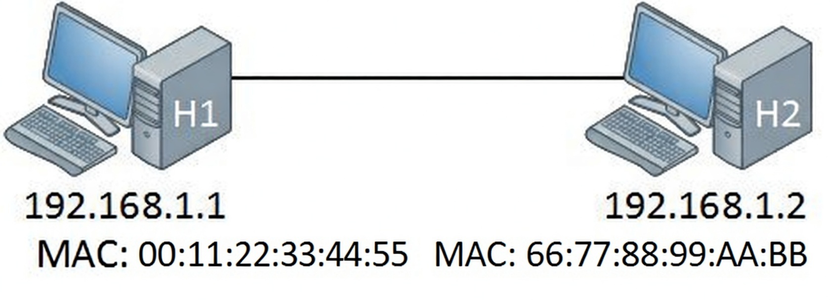
Consider a simple LAN with two hosts:
- H1: IP = 192.168.1.1, MAC = 00:0c:29:e7:0f:2e (often shown as AAA in simplified diagrams)
- H2: IP = 192.168.1.2, MAC = 00:0c:29:63:af:d0 (often shown as BBB)
From H1, you run:
C:\Users\H1> ping 192.168.1.2
Pinging 192.168.1.2 with 32 bytes of data:
Reply from 192.168.1.2: bytes=32 time=15ms TTL=57
Reply from 192.168.1.2: bytes=32 time=15ms TTL=57
Reply from 192.168.1.2: bytes=32 time=14ms TTL=57
Reply from 192.168.1.2: bytes=32 time=17ms TTL=57

Ping statistics for 192.168.1.2:
    Packets: Sent = 4, Received = 4, Lost = 0 (0% loss),
Approximate round trip times in milli-seconds:
    Minimum = 14ms, Maximum = 17ms, Average = 15ms
The ping uses ICMP (Layer 3) wrapped in an IPv4 packet (source IP 192.168.1.1 → destination IP 192.168.1.2). To send this over Ethernet, H1 needs to build a frame with its own MAC as source—but what about the destination MAC (H2’s)?
H1 doesn’t know it yet. ARP steps in to find out.
Viewing the ARP Table
After successful communication, H1 caches the mapping in its ARP table (also called ARP cache). View it with:
text
C:\Users\H1> arp -a

Interface: 192.168.1.1 --- 0xb
  Internet Address      Physical Address      Type
  192.168.1.2           00-0c-29-63-af-d0     dynamic
  192.168.1.255         ff-ff-ff-ff-ff-ff     static
  224.0.0.22            01-00-5e-00-00-16     static
  224.0.0.252           01-00-5e-00-00-fc     static
  239.255.255.250       01-00-5e-7f-ff-fa     static
255.255.255.255 ff-ff-ff-ff-ff-ff static- Dynamic entries (like 192.168.1.2) are learned via ARP.
- Static entries handle broadcasts (255.255.255.255) and multicasts (224.0.0.x).
This cache prevents repeated ARP queries, reducing broadcast traffic.
How ARP Works: Request and Reply Process
Assume H1’s ARP table is empty—no mapping for 192.168.1.2.
- H1 broadcasts an ARP Request: “Who has 192.168.1.2? Tell 192.168.1.1.”
- Destination MAC = FF:FF:FF:FF:FF:FF (broadcast) → floods to all LAN devices.
- All devices receive it, but only H2 (matching IP) replies.
- H2 sends a unicast ARP Reply: “192.168.1.2 is at 00:0c:29:63:af:d0.”
- Sent directly to H1’s MAC.
- H1 adds the entry to its ARP table and sends the original IP packet (now in Ethernet frame) to H2’s MAC.
Text-described diagram: H1 sends broadcast arrow labeled “ARP Request: Who has 192.168.1.2?” to the network cloud. All devices receive it. H2 sends unicast arrow back labeled “ARP Reply: 192.168.1.2 is at [MAC]”.
This process happens transparently before most Layer 3 traffic on the same subnet.
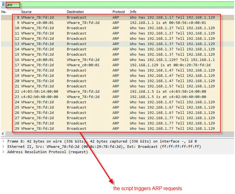
Capturing ARP with Wireshark
Wireshark reveals the exact packets. Here’s a typical capture:
- ARP Request (Frame 1): Broadcast from H1.
- ARP Reply (Frame 2): Unicast from H2.
ARP Request Packet Breakdown
text
Frame 1: 42 bytes on wire (336 bits), 42 bytes captured (336 bits) on interface 0
Ethernet II, Src: Vmware_e7:0f:2e (00:0c:29:e7:0f:2e), Dst: Broadcast (ff:ff:ff:ff:ff:ff)
Address Resolution Protocol (request)
    Hardware type: Ethernet (1)
    Protocol type: IP (0x0800)
    Hardware size: 6
    Protocol size: 4
    Opcode: request (1)
    Sender MAC address: Vmware_e7:0f:2e (00:0c:29:e7:0f:2e)
    Sender IP address: 192.168.1.1 (192.168.1.1)
    Target MAC address: 00:00:00_00:00:00 (00:00:00:00:00:00)
    Target IP address: 192.168.1.2 (192.168.1.2)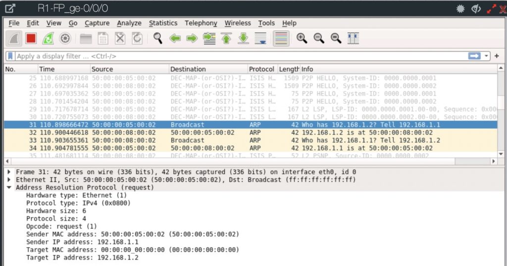
Note: Target MAC is all zeros—unknown.
ARP Reply Packet Breakdown
text
Frame 2: 42 bytes on wire (336 bits), 42 bytes captured (336 bits) on interface 0
Ethernet II, Src: Vmware_63:af:d0 (00:0c:29:63:af:d0), Dst: Vmware_e7:0f:2e (00:0c:29:e7:0f:2e)
Address Resolution Protocol (reply)
    Hardware type: Ethernet (1)
    Protocol type: IP (0x0800)
    Hardware size: 6
    Protocol size: 4
    Opcode: reply (2)
    Sender MAC address: Vmware_63:af:d0 (00:0c:29:63:af:d0)
    Sender IP address: 192.168.1.2 (192.168.1.2)
    Target MAC address: Vmware_e7:0f:2e (00:0c:29:e7:0f:2e)
    Target IP address: 192.168.1.1 (192.168.1.1)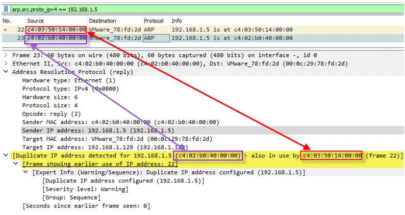
H2 fills in its own MAC as sender.
(These Wireshark images show real packet dissections—request broadcast and reply unicast—with key fields highlighted.)
Summary of Key Takeaways
- ARP resolves IPv4 addresses to MAC addresses for Ethernet encapsulation on the same LAN/subnet.
- It uses broadcast ARP requests (Opcode 1) and unicast ARP replies (Opcode 2).
- Mappings are stored in the ARP table (view with arp -a) as dynamic or static entries.
- Essential for understanding OSI Layer 2/3 interaction, ICMP pings, and local IPv4 communication.
- No ARP needed across routers (different subnets use gateway MAC instead).
Conclusion
ARP is a simple yet critical protocol that bridges the gap between IP addressing and physical hardware addressing. Mastering it helps troubleshoot connectivity issues, analyze traffic in Wireshark, and succeed in CCNA exams. Practice by running pings, checking ARP tables, and capturing packets in a lab environment.
For deeper reading, explore our guides on the OSI Model and IPv4 Packet Header.
ARP Knowledge Check
ARP stands for Address Resolution Protocol. Its main purpose is to map a known IPv4 address (Layer 3) to an unknown MAC address (Layer 2) so that devices on the same local network (LAN/subnet) can communicate using Ethernet frames.
ARP technically operates between Layer 2 (Data Link) and Layer 3 (Network). It is encapsulated directly in Ethernet frames (EtherType 0x0806) and is not carried inside an IP packet.
IP addresses are logical and used for routing across networks. However, on a local Ethernet network, frames are delivered using physical (MAC) addresses. ARP is needed because the sending device knows the destination IP but not the destination MAC — ARP discovers that missing piece.
This is the Ethernet broadcast address. When a device sends an ARP Request, it doesn’t know who has the target IP, so it broadcasts the question to every device on the local network. Only the device with the matching IP will respond.
It is set to 00:00:00:00:00:00. This is a placeholder because the sender does not know the target’s MAC address — that’s exactly what it’s asking for.
No. ARP is only used within the same broadcast domain / subnet. When devices are on different subnets, the sender ARPs for the default gateway’s (router’s) MAC address, not the final destination’s.
1. Windows / Linux: arp -a
2. Cisco IOS: show arp or show ip arp
Dynamic: Automatically learned through ARP replies. Most common. Ages out after a timeout (typically 4 hours on Windows, shorter on some devices).
Static: Manually configured (e.g., arp -s IP MAC on Windows). Does not age out. Used for security or special cases.
No. IPv6 uses NDP (Neighbor Discovery Protocol) instead of ARP. NDP uses ICMPv6 messages and multicast instead of broadcast.
Common causes:
– The target device is powered off or disconnected
– Wrong subnet / IP misconfiguration
– Firewall blocking ARP (very rare)
– Proxy ARP disabled on router when needed
– Device is not responding to ARP requests
Yes — the most common attack is ARP spoofing / ARP poisoning, where an attacker sends fake ARP replies to associate their MAC with another device’s IP (usually the default gateway). This allows man-in-the-middle attacks.
0x0806
42 bytes (including Ethernet header).
Ethernet header = 14 bytes
ARP payload = 28 bytes
Opcode 1 = Request
Opcode 2 = Reply
Keep practicing—these concepts build the foundation for all local network troubleshooting!